A. Version History
|
Date |
Revision |
Description |
Author |
|
2018-11-15 |
A |
Documents created with features in subsequent revisions |
Vinh Nguyen canvinh@gmail.com |
|
2020-09-10 |
PB1 |
Added section 35 for number portability used by Telco or subscriber relocation |
Vinh Nguyen |
|
2020-09-11 |
PB2 |
Update section 35 for an option to use subscriber credentials replacing PIN code |
Vinh Nguyen |
|
2021-07-12 |
PB3 |
Adding section 36 for handling of military mobile phone also registered as a VoIP phone |
Vinh Nguyen |
|
2022-04-05 |
PB4 |
Adding section 37 for handling phone calls using satellite networks |
Vinh Nguyen |
|
2022-12-23 |
PB5 |
Add some clarification in the section 37 |
Vinh Nguyen |
B. System Descriptions


The visiting server doesn’t have information of a visitor until the home server authorized and agreed.

6. International Call Delivery
8. Prepaid long distance call

As shown in figure 4, the home center server would keep track and manage prepaid accounts especially in international roaming. The remaining minutes roaming calls would be sent by the home server to the serving RBS server, and finally delivered to its subscriber by the serving RBS.
The personalized disconnect message would be relayed to its subscriber by the RBS server.
9. Military deployment without Subscriber Location server

In case of military deployment, station space is limited. Mobile subscribers or military personnel would contact each other in the same location or commanders at the central server most of the time. There is no need to deploy a Subscriber Location server. The RBS would be configured to request registration, call from, or call delivery permissions directly to its local central server, i.e. by pass the usual steps with a Subscriber Location server. All long distance calls would be handled by the central server connecting with other servers via its satellite gateway as usual.
Currently military plans to share its telecom network with federal employees. The military network will cover the entire country. However there are no federal offices in some states, thus Location Server is not needed. The (special configured) RBS would request registration, call delivery to a subscriber through its local central server directly. The visiting central server would perform the request for permissions of registration and call deliver to visitor's home server. Any central server has a database of telecom network anyway. The message would include its OPC (sender IP) and RBS’s IP to differentiate this request and usual request by an RBS. By the way, a pair (mirror servers) of Subscriber Location server is not very expensive, thus having its installed make configuration simpler. IT staff from a state can figure out the configuration of a telecom system in another state easily, i.e. no exception.
The only change in the RBS to support no-Subscriber Location server could be to replace the IP address of the Subscriber Location Server with the IP address of the visiting central server for permissions of registration and call delivery for a mobile subscriber. The visiting central server would have similar codes (which were developed for RBS communicating with a Subscriber Location server) as the RBS with its own IP address as the sender.
Business calls used special RBS voice packets, i.e. not a standard mobile phone voice. At the beginning this telecom system is only intended for military used, so there was no need to convert RBS voice to popular voice standard such as ISUP. There is a new requirement to setup calls to external telecom operators, thus based on the dialed number, the originating central server would convert its RBS voice to a standard mobile telephony’s voice before sending messages out, so public telecom network could understand.
Personal calls are only allowed to all free long distance calls, e.g. calls to Canada or USA. This could be implemented in any central server with a special class, e.g.
11. Satellite Internet
There are many companies and organizations have satellites in orbits including USA, Canada, Russia, Europe, and Israel. Some of those satellite networks are strictly for military use. However some of them were phased out and replaced by modern satellites. We could update those obsolete satellites to provide Internet to remote zones with reasonable monthly fees.
Remote Internet service providers (ISP) needs to do followings
There are not many satellites in the sky, and space agency knew all existing or new satellites in orbits. Therefore, space agencies could implement a routing network for satellites from different national providers to transfer data effectively for Internet as well as phone communications.
The satellite networks must support 2 routing methods, i.e. one for military use and the other for public. This could be done as follows
11.1 Indicators
Each satellite gateway could be configured with 2 indicators:
Router would route military users’ traffic to the (nearest) destination base based on destination IP address using appropriate satellite networks.
All public users’ traffic would be routed to a dedicated base in each country.
11.3 Routing by satellite networks
There are fewer satellites in a network than number of landline ISP or nodes, so satellite providers could team up to develop a special routing table for data transfer, i.e. kind of hard coded in database. For example, with knowledge of sender IP, destination IP, users, etc. There are special columns in database such as column #1 for originating node, #2 transfer node (could be another network, e.g. from USA to Russia), #3 destination node (could be a dedicated landline node). If a new satellite is in orbit, satellite providers only need to look at their map of all satellites and change routing database accordingly. There are not many new satellites per decade anyway.
12. Gateway communications with a central server
The telecom system has standard protocol to inform server the end of conversation, i.e. duration of calls. Thus voice communication is not needed unless operators want a statistic for amount of data used in voice communications per user or entire system.
A statistic report, which could also be used for billings, should include timestamp, sender, receiver, Internet or voice, gateways involved in communications, amount of data transfer, etc. Each RBS server should also be considered as a gateway as it could send voice packets to other RBS servers or other gateways. Operators could generate a final monthly report for each user, entire base, voice data transfer, Internet data transfer, etc.

To make similarity with other diagrams, OPP home server is like a visiting central server, and other city police servers operated as home central servers. From telco point of view, OPP home server is like the main server owned spectrum and RBS servers, other city police servers are like sub-contracting servers selling telephony services.
If (area code 416 or 905) Markham user (GTA) visited Kingston (remote city) and registered there, Kingston serving RBS Box would send a query request to its Subscriber Location server for the home server IP of that GTA user. Kingston’s Location Server would send a request to GTA’s Location Server (416 and 905 area codes) to obtain the home server IP of that Markham user and return it to Kingston’s Subscriber Location server, which in turn relayed information to the serving RBS. The serving RBS would contact Markham as the home server. Process would be similar to scenario of a visitor registered or made calls, which were described in other sections. [This scenario is probably the efficient way to deliver a call to a GTA user; however, telco may require call case setup by home/main server instead of a sub-contract server for charging capability.] See the charging scenarios’ diagrams for details of routing or setting up a call.


An RBS should include information about calling party, called party, and other data such as originating node IP, terminating node IP while setting up a call in request for setup call to its home server. Some information was from Subscriber Location server, originating RBS server, originating visitor’s home server, etc. depending on each call scenario. This helps its central server to match data in order to prevent frauds.


21.2 Encoding and encrypting strategy

23.1 Common settings
23.2 Navy
25.1 Military and Police network
25.2 Telecom operator’s network
26. Navy Fleet communications
27. Alternative routing of services
It is assumed that the main server owned the spectrum and leased its wireless network to subcontract server selling air time. The main server would receive charging data from other network operators in case of either its subscribers or subcontract server’s servers roam in another wireless networks. Therefore the main server would request subcontract server to authorize a roaming call request for its subscriber internally, but main server would handle authorization or agree to roaming charges with other network operators instead of subcontract server.


In figure 18, MS2 ended call. This is a call case of a subcontracted user made a call and then the called party hung up. The main server handling of “ended call” user would inform the subcontracted server (MS1 Home subcontract server); and MS1 & MS2’s central servers (MS1 & MS2 main server) about call time.

29. Backup system for phone calls or Internet services
In order to provide 24/7 services to a base in case of interrupted
local central server, each RBS box would be configured to recognize the
military head quarter server as a backup server.
·
Military server would store all subscribers
of its forces in database. Those records would be active, but does not have any
activity or updated by local servers normally. That means local servers do not
need to update head quarter servers for daily activities of its subscribers.
·
Each RBS box would recognize the head quarter
server as a legitimate central server
·
The communication between an RBS box with
head quarter server would be common encryption, i.e. head quarter doesn’t need
to store private encryption used by each military base.
·
Usually each phone call setup would be
allowed within 1 minute. If a call could not be set up within a minute, system
would automatically disconnect all parties concerned to avoid hanging records
(zombie) in the system.
·
A local central server could be down for a
reason during a call request. If a call placed from an RBS could not be
completed within, e.g. 20 seconds, that RBS would attempt to connect with the
head quarter server to complete the call setup.
·
Head quarter server would set up call for
that user, and this is the only time the head quarter server stores data
related to that call for billing purposes.
·
If the local server was up after 20 seconds
and attempted to connect with that user’s RBS, the RBS should send a disconnect
message to the local central server to release its records. The call should be
handled by the head quarter server to simplify software implementation.
There should be only one backup system, i.e. head quarter server,
because military does not want head quarter data stored at any local base.
A subscription or features allocated to each user could be different in a local central server and its head quarter server for security and usage purpose. For example, a California user could surf Internet using satellite, but at its head quarter that user could not use Internet or only Internet via regular cable.
30. Encryption policy
To make hacking activity harder, each military base would be
responsible to their private or local protocol encryption, i.e. head quarter
doesn’t know the over the air private encryption used by each base. Hacking
activity would likely be concentrated in head quarter; therefore this was a
risk of disposing over the air encryption’ security of local base, if hacked.
Hackers would be forced to come to each base and attempted to hack to the local
network.
To safeguard local over-the-air encryption, mobile phone would be
synchronized with new (daily or weekly change) encryption by placing its
handset into a personal cradle connected to local network.
Visitors to a base would be required to sync their handsets in an
IT control room to get local encryption in order to make or receive phone
calls.
Because protocol encryption could be easily implemented or
designed by many software developers, the tasks to track down the author or
obtaining the algorithms would be very difficult to hackers. Telephony system
providers could hand over this security task to each military force.
For Telco, they may offer both common over-the-air encryption and
private encryption to their subscribers downloaded over the air. Private
subscribers would communicate with the local RBS or RBS server using private
encryption. Visitors form another Telco would use common encryption, because
their phone numbers are identified as visiting roamers. The common encryption
could be updated by all Telco over the computer networks.
31.
Internet, RAN and
Central RAN
Usually a RAN is connected to an RBS and sending data to its
central RAN before dispatching to destination.
In this configuration the Internet communication from a handset
would go to the associated RBS server, where first packet of data would go the
central server to determine proper gateway to destination, such as Internet
Gateway, satellite gateway, WLAN gateway, etc. To make it compatible to 5G
system, those data packet would be encapsulated in an IP envelope (relevant
heading of those packets could be removed and then added later at destination
server) and send out toward its central RAN via selected gateway.
However the central server could add an indicator based on its
analysis of the packet’s destination, i.e. within IP telephony network, it
could remove the entire data packet heading or sending it directly to a central
server at destination. The proprietary IP protocol could be used. This is
optional for system developers as it is more complicated to develop, but
processing time for sending each packet to destination would be faster.
By the way for telco 5G stuff, APY is very powerful for using as a
platform of an RBS. The RAN could be incorporated into the APY to lower product
costs. With this the RBS could send data directly to its central RAN. It should
be faster and more efficient.
32.
Mobile Router Handling
Sub-systems

As shown in the figure 20, there are two Wireless Envelope Final Packing and Unpacking subsystems
interfacing the wireless network for mobile telephony, i.e. one for military
system and one for regular Telco network.
Military handset used proprietary frequencies, so it cannot roam
in any regular Telco network. To make military handset roam-able, it must be
able to handle public air wave spectrums. To make military phone secured, each
handset should be loaded with separate mobile telephony system used by Telco,
i.e. Mobile Telephony Subsystem for Telco
Network. All phone calls using public airwaves would be handled by this
subsystem, i.e. military software is safeguarded or untouched.
The only issue would be handling of devices connecting to a
military handset via WiFi interface, i.e. handset acted as a mobile router. There
are 3 cases, i.e.
a) Military
staff using a military laptop to login its military network via the WiFi router.
This laptop should have a unique indicator recognized by the handset during exchanging
messages with the WiFi System Interface
Manager. Military staff is not recommended to use his “proprietary” laptop
using public wireless network. The less exposing of sensitive equipment to
public would be better in terms of security.
b) Public
laptops or tablets used by children or military staff to access public network
via military wireless system.
c) Public laptops or tablets used by children or military
staff to access public network via Telco wireless system.
In case of (a), all message exchanged by the military laptop would
be handled by the WiFi Packet Unpack and
Pack Unit for Military subsystem. This system would simply unpack packet
and preliminary pack data in required format before passing those to the WiFi System Interface Manager or Wireless Envelope Final Packing and
Unpacking for Military Network for final
processing including encryption and relevant packet envelope(s).
In case of (b), all message exchanged by the public laptop would
be handled by the WiFi Packet Unpack and
Pack Unit for Telco subsystem. This system would simply unpack packet and
preliminary pack data in required format before passing those to the WiFi System Interface Manager or System Interface Manager or Wireless Envelope Final Packing and
Unpacking for Military Network for final
processing including encryption and relevant packet envelope(s). (If you
wanted the WiFi Packet Unpack and Pack
Unit for Military subsystem to handle packing and unpacking tasks, the
system must know in advance that the handset is currently in military wireless
network, i.e. system is well integrated. By using Telco packing and unpacking
subsystem, the entire system is loosely coupled, WiFi Interface Unit only checks
for military indicator from a WiFi
message.)
In case of (c), all message exchanged by the any public laptop
would be handled by the WiFi Packet
Unpack and Pack Unit for Telco subsystem. This system would simply unpack
packet and preliminary pack data in required format before passing those to the
WiFi System Interface Manager or Wireless Envelope Final Packing and
Unpacking for Telco Network for final
processing including encryption and relevant packet envelope(s).
The above discussion is for dual mode mobile handsets using both
military and public wireless network, i.e. 2 WiFi Pack and Unpack Units running separately. If military decided
its handset is single mode, i.e. only used within military wireless network,
then only a WiFi Pack and Unpack Unit is needed.
33.
Internet and mobile phone
network in rural areas
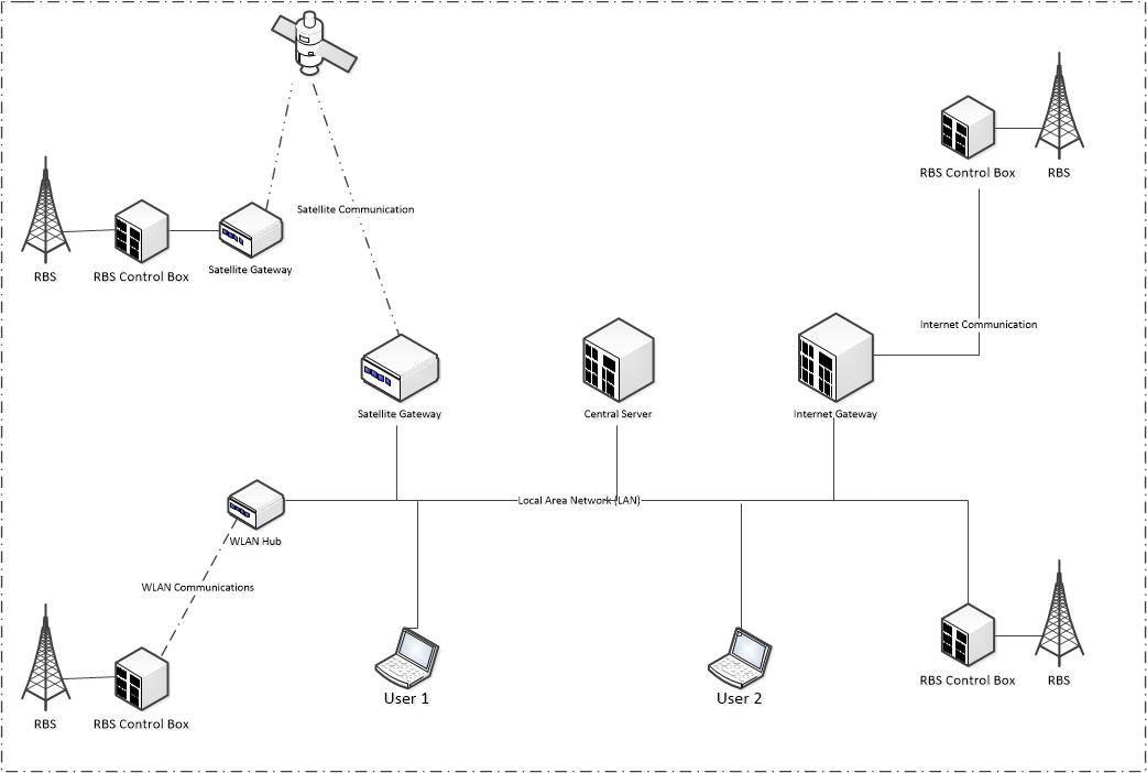
By looking at the main diagram, we could see that communications
between servers or RBS Boxes could be Internet or satellites.
Satellites communications are generally expensive for heavily
usage.
Governments usually require network operators to provide Internet
or phone communications in rural areas in order to own airwave spectrum for
mobile telephony operations. Mobile operators could team up with an Internet
operator to run fiber optical cables in small cities or rural areas to provide
Internet services. Those locations could be connected to nearest larger city
for full services using fiber optical cables or satellites. RBS Boxes and radio
base stations could be installed in these remote locations to provide wireless
access or telephony. RBS Boxes would be connected together using Internet
lines. This would save both Internet Service Provider and Telco operators.
34.
Leasing RBS capacity to Telco
wireless operators.
Military network (or police) network would cover the entire
country with Radio Base Stations (RBS). However their usage is very low, thus
Radio Base Station would be operated at very low processing power, i.e. under
usage.
Military could lease its RBS capacity, especially in rural areas,
to reliable Telco wireless operator(s). Telco would be responsible to sell its
services and handle communications to public users according to telecommunication
industry standards as well as providing a spectrum for RBS, i.e. each RBS
operates with 2 different spectrums in parallel; one for military (police) and
one for general public.
Military would load Telco’s telephony system on RBS to run it in
parallel with military telephony system. Note that military system has
different encryption and features for military users. There would be a
subcontract server handles public users in this case. Military would handle the
maintenance operations of this wireless network, and send monthly public user
information, billing information, etc. to Telco, i.e. a part of data stored in
the subcontract server.
Since military and police have policy to safeguard their networks
to outsiders, having part of networks leased would make them think twice. To
make their policy less impacted, public (leased) call’s traffic must be routed to
the nearest gateway to public network or as soon as possible, i.e. having less
public traffic in internal network. It should be noted that military and police
has extra network capacity, thus they would likely help residents in rural
areas with mobile telephony access via leasing its RBS and partial network to a
Telco operator.
Let’s MS-A be the calling party and MS-B be the called party. MS-A
and MS-B could be either a military (police) staff or a public user. We are
concerned with the calling party phone number, because it would determine call
traffic originated by a public user. By browsing call setup traffic’s diagrams
in sections above, MS-A and MS-B were included in the sequence of messages.
Therefore the mobile telephony network could redirect all calls involved public
user based on MS-A to nearest public network via a gateway.
MS-B is irrelevant in this case as a military (police) staff could
call to an internal colleague or a public user, where calls would be routed via
military’s (police’s) network to the nearest gateway closed to the called
party, MS-B.
35.
Phone Number Portability or
Subscriber Relocation
To automate the process of a subscriber moving from a city to
another city or changing telecom operators easily, telecom operator should
assign a PIN code, which should include digits and alphabets, associated with
the phone number. For example,
If a subscriber registered with Bell Canada in Quebec, Bell would
give subscriber a phone number, e.g. 514-678-3425, and a PIN code such as
BELLQC34526. The registration process was performed in the Subscriber Location
Server and its home central server (serving the phone user) would be updated
automatically by messages. The phone user should safe guard this PIN code.
Assuming the subscriber moved from Quebec to Toronto of Ontario and registered
with Rogers. Rogers would assign the subscriber with a Toronto phone number,
e.g. 416-786-9879, and another PIN code ROGERON2456. In the registration
process in the Rogers’ telephony system at their Subscriber Location Server
(SLS), the SLS would send a deregistration request to the SLS of Bell Canada in
Quebec for the subscriber including his old phone number (514-678-3425) and
associated PIN code (BELLQC34526). SLS in Quebec would update (or remove the
subscriber record in) its database and also update record of relevant home central
server automatically. This process would be automated with that confidential
PIN code.
The process of phone number portability would be performed when a
subscriber was switching from a telco to another telco in the same city or
area. It could be done with the same automatic process as described above for
subscriber’s relocation by using his confidential PIN code.
If a subscriber lost his PIN code, the operator must contact the
previous operator and carry out deregistration process manually.
The idea was using previous subscriber phone number as username
and his PIN code as password in automatic deregistration process.
There is a way to automate deregistration process if user lost his
previous PIN code. The password could be his full name or previous address
including postal code. It is up to telecom operators to select which
information was credible enough to replace the PIN code to automate
deregistration process.
31. Internet, RAN and Central RAN
Usually a RAN is connected to an RBS and sending data to its central RAN before dispatching to destination.
In this configuration the Internet communication from a handset would go to the associated RBS server, where first packet of data would go the central server to determine proper gateway to destination, such as Internet Gateway, satellite gateway, WLAN gateway, etc. To make it compatible to 5G system, those data packet would be encapsulated in an IP envelope (relevant heading of those packets could be removed and then added later at destination server) and send out toward its central RAN via selected gateway.
However the central server could add an indicator based on its analysis of the packet’s destination, i.e. within IP telephony network, it could remove the entire data packet heading or sending it directly to a central server at destination. The proprietary IP protocol could be used. This is optional for system developers as it is more complicated to develop, but processing time for sending each packet to destination would be faster.
By the way for telco 5G stuff, APY is very powerful for using as a platform of an RBS. The RAN could be incorporated into the APY to lower product costs. With this the RBS could send data directly to its central RAN. It should be faster and more efficient.
32. Mobile Router Handling Sub-systems

As shown in the figure 20, there are two Wireless Envelope Final Packing and Unpacking subsystems interfacing the wireless network for mobile telephony, i.e. one for military system and one for regular Telco network.
Military handset used proprietary frequencies, so it cannot roam in any regular Telco network. To make military handset roam-able, it must be able to handle public air wave spectrums. To make military phone secured, each handset should be loaded with separate mobile telephony system used by Telco, i.e. Mobile Telephony Subsystem for Telco Network. All phone calls using public airwaves would be handled by this subsystem, i.e. military software is safeguarded or untouched.
The only issue would be handling of devices connecting to a military handset via WiFi interface, i.e. handset acted as a mobile router. There are 3 cases, i.e.
a) Military staff using a military laptop to login its military network via the WiFi router. This laptop should have a unique indicator recognized by the handset during exchanging messages with the WiFi System Interface Manager. Military staff is not recommended to use his “proprietary” laptop using public wireless network. The less exposing of sensitive equipment to public would be better in terms of security.
b) Public laptops or tablets used by children or military staff to access public network via military wireless system.
c) Public laptops or tablets used by children or military staff to access public network via Telco wireless system.
In case of (a), all message exchanged by the military laptop would be handled by the WiFi Packet Unpack and Pack Unit for Military subsystem. This system would simply unpack packet and preliminary pack data in required format before passing those to the WiFi System Interface Manager or Wireless Envelope Final Packing and Unpacking for Military Network for final processing including encryption and relevant packet envelope(s).
In case of (b), all message exchanged by the public laptop would be handled by the WiFi Packet Unpack and Pack Unit for Telco subsystem. This system would simply unpack packet and preliminary pack data in required format before passing those to the WiFi System Interface Manager or System Interface Manager or Wireless Envelope Final Packing and Unpacking for Military Network for final processing including encryption and relevant packet envelope(s). (If you wanted the WiFi Packet Unpack and Pack Unit for Military subsystem to handle packing and unpacking tasks, the system must know in advance that the handset is currently in military wireless network, i.e. system is well integrated. By using Telco packing and unpacking subsystem, the entire system is loosely coupled, WiFi Interface Unit only checks for military indicator from a WiFi message.)
In case of (c), all message exchanged by the any public laptop would be handled by the WiFi Packet Unpack and Pack Unit for Telco subsystem. This system would simply unpack packet and preliminary pack data in required format before passing those to the WiFi System Interface Manager or Wireless Envelope Final Packing and Unpacking for Telco Network for final processing including encryption and relevant packet envelope(s).
The above discussion is for dual mode mobile handsets using both military and public wireless network, i.e. 2 WiFi Pack and Unpack Units running separately. If military decided its handset is single mode, i.e. only used within military wireless network, then only a WiFi Pack and Unpack Unit is needed.
33. Internet and mobile phone network in rural areas
By looking at the main diagram, we could see that communications between servers or RBS Boxes could be Internet or satellites.
Satellites communications are generally expensive for heavily usage.
Governments usually require network operators to provide Internet or phone communications in rural areas in order to own airwave spectrum for mobile telephony operations. Mobile operators could team up with an Internet operator to run fiber optical cables in small cities or rural areas to provide Internet services. Those locations could be connected to nearest larger city for full services using fiber optical cables or satellites. RBS Boxes and radio base stations could be installed in these remote locations to provide wireless access or telephony. RBS Boxes would be connected together using Internet lines. This would save both Internet Service Provider and Telco operators.
34. Internet and mobile phone network in rural areas
Military network (or police) network would cover the entire country with Radio Base Stations (RBS). However their usage is very low, thus Radio Base Station would be operated at very low processing power, i.e. under usage.
Military could lease its RBS capacity, especially in rural areas, to reliable Telco wireless operator(s). Telco would be responsible to sell its services and handle communications to public users according to telecommunication industry standards as well as providing a spectrum for RBS, i.e. each RBS operates with 2 different spectrums in parallel; one for military (police) and one for general public.
Military would load Telco’s telephony system on RBS to run it in parallel with military telephony system. Note that military system has different encryption and features for military users. There would be a subcontract server handles public users in this case. Military would handle the maintenance operations of this wireless network, and send monthly public user information, billing information, etc. to Telco, i.e. a part of data stored in the subcontract server.
Since military and police have policy to safeguard their networks to outsiders, having part of networks leased would make them think twice. To make their policy less impacted, public (leased) call’s traffic must be routed to the nearest gateway to public network or as soon as possible, i.e. having less public traffic in internal network. It should be noted that military and police has extra network capacity, thus they would likely help residents in rural areas with mobile telephony access via leasing its RBS and partial network to a Telco operator.
Let’s MS-A be the calling party and MS-B be the called party. MS-A and MS-B could be either a military (police) staff or a public user. We are concerned with the calling party phone number, because it would determine call traffic originated by a public user. By browsing call setup traffic’s diagrams in sections above, MS-A and MS-B were included in the sequence of messages. Therefore the mobile telephony network could redirect all calls involved public user based on MS-A to nearest public network via a gateway.
MS-B is irrelevant in this case as a military (police) staff could call to an internal colleague or a public user, where calls would be routed via military’s (police’s) network to the nearest gateway closed to the called party, MS-B.
35. Phone Number Portability or Subscriber Relocation
To automate the process of a subscriber moving from a city to another city or changing telecom operators easily, telecom operator should assign a PIN code, which should include digits and alphabets, associated with the phone number. For example,
If a subscriber registered with Bell Canada in Quebec, Bell would give subscriber a phone number, e.g. 514-678-3425, and a PIN code such as BELLQC34526. The registration process was performed in the Subscriber Location Server and its home central server (serving the phone user) would be updated automatically by messages. The phone user should safe guard this PIN code. Assuming the subscriber moved from Quebec to Toronto of Ontario and registered with Rogers. Rogers would assign the subscriber with a Toronto phone number, e.g. 416-786-9879, and another PIN code ROGERON2456. In the registration process in the Rogers’ telephony system at their Subscriber Location Server (SLS), the SLS would send a deregistration request to the SLS of Bell Canada in Quebec for the subscriber including his old phone number (514-678-3425) and associated PIN code (BELLQC34526). SLS in Quebec would update (or remove the subscriber record in) its database and also update record of relevant home central server automatically. This process would be automated with that confidential PIN code.
The process of phone number portability would be performed when a subscriber was switching from a telco to another telco in the same city or area. It could be done with the same automatic process as described above for subscriber’s relocation by using his confidential PIN code.
If a subscriber lost his PIN code, the operator must contact the previous operator and carry out deregistration process manually.
The idea was using previous subscriber phone number as username and his PIN code as password in automatic deregistration process.
There is a way to automate deregistration process if user lost his previous PIN code. The password could be his full name or previous address including postal code. It is up to telecom operators to select which information was credible enough to replace the PIN code to automate deregistration process.
36. Dual mode mobile phone and VoIP phone
During the early days of deployment this mobile telephony system for military and police, 5G phones could only be supported by a military frequency, and military didn’t want it roaming to a telco networks as well as signaling used in military’s mobile telephone network different than telco, i.e. proprietary IP signaling and private encryption.
In order to make phones used or recognized by worldwide telecom networks, each military phone could be registered as a VoIP phone. All incoming calls routed to its central home server, where call processing would be started as for a mobile phone within military network. This was the simplest and fastest way to make system up and running quickly.
To make its mobile phone able to roam to a public telecom network in addition to install a public mobile system on the phone in parallel with military mobile system, there are 2 solutions
· Each mobile phone would be registered as a mobile phone instead of VoIP phone
This solution may require additional work to update phone worldwide telco’s database. Telco system must recognize a home central server as an HLR and support IP communication, i.e. installing an IP node to convert IP signals or messages into their existing SS7 or C7 messages OR
· Updating telco’s MSC to recognize a mobile phone could be functioned as both VoIP phone and mobile phone, so routing, paging, and charging functions could be carried out properly.
Usually when we dialed a landline phone number, MSC would route call request through a voice trunk, e.g. BT4 or ISUP, without involving the process of authenticating, locating, paging, and routing call to a mobile phone.
If a dual mode phone roamed to a public network and dial a number, the MSC would send a request to its (IP) home central server for authentication and authorization instead to its “home HLR” via SS7 signaling. The home central server would behave as either landline MSC or home HLR depending on the state or location of its mobile phone.
Military must install a gateway node to convert SS7 messages into IP messages for processing OR each telco would convert SS7 message into IP messages before sending out via Internet.
If telecom operators planned to deploy or use this IP mobile telephony system, they should implement nodes to convert SS7 or C7 messages in IP messages to communicate to military networks.
37. Handling of phone calls for remote users with satellite networks
This telephony system could be used for users in remote areas with satellite networks dispatching phone calls to a designated central server.
In scenario 1: assuming that an African user in a remote village places a phone call with local telecom operator to a user in California,
· The serving satellite operator (e.g. Telesat) doesn’t have any satellite in California or USA, but has a special agreement with Bell Mobility (wireless telco in Canada) and satellite in Canada.
· Call would be routed by satellite to Canada and connected to Bell Mobility network or central server
· Bell Mobility would route this call to the user in California by its network as usual
· The only draw back in this solution is “charging.” This (probably poor) user should be charge a “low” roaming fees.
· This call may be required by regulator to label as call routed by both satellite and mobile telephony networks.
· With African phone number, an indicator of Telesat, and Bell Mobility’s sender IP, we could tell the identity and how call was transferred.
In scenario 2: assuming passengers of a cross nationwide train wanted to place calls and surfing Internet on board. Usually they’re using GSM-R system for this, but we could also use this telephony system. Assuming passengers are travelling from Nova Scotia (Eastern Canada) to Vancouver of British Columbia (Western Canada).
· Equipping the train wagons with sufficient capacity for passengers by using RBS and its RBS box.
· The train could use Nova Scotia’s central server as its home servers and its passengers as roamers.
· Passengers could connect to the on-train RBS and is RBS box, which is communicated with satellite system such as Telesat during the journey.
· All calls or Internet traffic would be transferred back to the central server in Nova Scotia regardless of its location such as Quebec, Ontario, Manitoba, Alberta, etc.
· Calls and Internet traffics would be handled by central server in Nova Scotia.
· Similar as above arguments for call by African caller, calls and Internet usages must be charged with reasonable rates.
· And all traffics would be “labeled” as traffics by both satellite and land systems.
For cross-border trains from Canada to USA, the RBS box should still use Telesat satellite network in USA (or other satellite operator if they’re inter-connected) to communicate or relay communications back to Nova Scotia central server to complete call or Internet traffics with destination users. The reason for not using RBS box to communicate with a central server of another telecom operator in USA is “private” communications implemented between an RBS box and its dedicated central server. Satellites are considered as transport layers for on land telecom.
In case of roaming train originated in Canada to USA, where the original satellite operators (Telesat) doesn’t have satellites, the train could switch to the US satellite operator (previously in agreement) to handle call and Internet traffics for its passengers. If the US satellite operator doesn’t have satellites in Canada or inter-connected with Telesat, the passenger’s voice/data traffics would be routed to an on-ground ISP (in USA) operated by the US satellite network. This ISP would then route traffics toward the central server of that RBS box by using Internet for further processing, e.g. central server in Nova Scotia. Of course the central server in Nova Scotia would communicate with this ISP for handling traffics with its moving RBS Box via the US satellite network.
The main reason to beam down traffic to an ISP in USA, where it will be routed to the central server in Nova Scotia, was to use on the ground infrastructure. In general, satellite system belongs to military. Military would kick out everyone to take over the entire satellite system, if needed. Therefore having traffic on the ground would safeguard those communications.
Military communications could be hand-off between different satellite systems, if they wanted. However civil communications should avoid relying on satellite networks as much as you can for the reason above.
Q: What is the difference between CDMA and TDMA?
ReplyDeleteA: These are two very different methodologies use to accomplish the same task, use frequency spectrum much more efficiently than the traditional dedicated fixed frequency transmitting system. The goal is to dramatically increase the number of essentially simultaneous users within a specific portion of radio spectrum. Both methods accomplish this.
CDMA is short for Code-Division Multiple Access, a digital cellular technology that uses spread-spectrum techniques. CDMA does not assign a specific frequency for each user placing or receiving a call. Individual conversations are encoded with a pseudo-random digital sequence scheme. The receiving equipment must be able to decode the received signal by having the ability to replicate this pseudo-random digital sequencing.
CDMA is actually a military technology first used during World War II by the English allies to foil German attempts at jamming radio transmissions. The allies transmitted different parts of important information over several frequencies, instead of a single frequency, hence making it considerably more difficult for the Germans to pick up and assimilate the complete signal. Because Qualcomm, Inc., created the communication chips for CDMA technology, it had access to the classified information, and once the information became available to the public, they became the first to commercialize it.
TDMA is short for Time Division Multiple Access, a technology for delivering digital wireless service using time-division multiplexing (TDM). TDMA technology divides a radio frequency into time slots and then allocates these time slots to multiple calls. In this way, a single frequency can support multiple, simultaneous data channels. The receiving equipment must be able to decode the received signal by decoding the received signal and reconstitute it using the same time slot selection algorithm as was used when it was encoded and transmitted. TDMA is used by the GSM digital cellular system.
Comparison factors:
All R wireless systems produce a decreasing signal as the distance between the transmitter and the receiver increase. In the simplest model, free space, the doubling the distance reduces the received signal level by the square of the ratio of change in distance. More sophisticated propagation modeling, which is widely used in the industry, will reveal that the relationship is far more volatile than the inverse of the square of the distance. With the use of CDMA and TDMA performance measurements exhibit that the degradation can be to the inverse of third or fourth order, making the proper selection of a desired receiver threshold even more important than with a conventional FM two-way radio modeling.
As an example, in a perfect world a CDMA phone might be able to provide adequate service with a received signal level of -106 dBm, where a phone employing TDMA must require -99 dBm of received signal level. However, it would be erroneous to infer that CDMA is always the preferred technology, because it can suitably operate with 7 dB less signal. The real life applications are not perfect. Building penetration will not be the same for both methods. Having the same signal level on both systems does NOT mean that the level of suitability of performance will be equal.
How does all this impact my received signal strength in order to have reliable wireless voice and data links when I use TAP for coverage predictions?
ReplyDeleteThe bottom line is for a digital portable radio or cell phone to have satisfactory no matter what the encryption method, it must have a received signal level sufficient for the information to be preselected and decoded and hence reconstitute the originally transmitted data stream. This means that you must identify the required signal level in either dBm or microvolts that must be present at the receiver for reliable performance. This is the signal level that you must select and plot when producing a radio coverage map. In general the actual threshold needed will be different from a CDMA encoded radio from that which uses TDMA. Due to the characteristics of the encoding, both will likely (but not always) require a higher threshold than a conventional FM modulated radio system assuming everything is properly aligned and tuned. In any event the best method for selecting the level you wish to specify when you wish to plot radio coverage would be to use a threshold specified by the equipment manufacturer and perhaps increase that threshold slightly based on your own personal measurements on a system already in service using the particular technology.
When you decide to go into greater detail and plot different conditions of coverage based on traffic, you will need to specify the pertinent threshold you wish for that particular condition. TAP will allow you to plot multiple thresholds on the same plot and thereby even see where coverage will be degraded as nuances of signal degrade from time to time based on any conditions including traffic as long as you specify the desired threshold ranges you wish to plot.
Source: https://www.softwright.com/faq/engineering/cdmatdma.html
CDMA is not a superior air interface standard as compared to TDMA as both methods encoded air messages with an algorithm.
ReplyDeleteBy the way, QUALCOMM developed CDMA for military, thus they can charged everyone with hefty fees.
If we based our network design on TDMA standard, we would save significant amount of money on royalty fees charged by Qualcomm. TDMA is a good standard by the way.
ReplyDeleteChanging the air interface standard would be a complicated task, thus we should keep CDMA air interface until 6G, which is a complete new standard. Decision would be based on performance & spectrum available by that time.
"TDMA
ReplyDeleteTDMA is an abbreviation of “Time-Division Multiple Access”. TDMA chops or divides the channel into sequential time portions. Users of the channel will have their respective round-robin turns in receiving and transmitting data. Breaking it down, only a single user is actually utilizing the channel at any given instance. Each user only uses the channel in short bursts at a time and that grant to use resources is given up for a while to also allow others to use the channel.
Actually, TDMA has been included into GSM for a very long time as it is already considered an old technology and it is beginning to become obsolete.
CDMA
CDMA is short for “Code-Division Multiple Access” and it is also a kind of multiplexing that allows several signals to use a single transmission channel.
CDMA, unlike TDMA, virtually allows numerous users to use the channel at the same time. Thus, transmitting and receiving are all done by various users simultaneously. This is only made possible by a process called Spread Spectrum, a type of modulation that captures every user’s flow of digital bits and spreads them all around the channel in a pseudo-random manner. The receiving end just interprets the scattered bits or in other words, un-randomize the bits to make them coherent
Of the two technologies, CDMA is the later one. Essentially, it emerged to resolve the inadequacies and the setbacks associated with TDMA."
Source: http://www.differencebetween.net/technology/difference-between-tdma-and-cdma/
* The question is "if TDMA could offer connections to the same number of users as CDMA or not." Capacity?
If you had little brains in your head, you must know that military, especially US military, don't want others using the system that they're using. Therefore if you wanted to use anything in this system, you must get permissions from international military including US military.
ReplyDeleteChinese always steal from others without respecting intellectual property rights. They will copy/steal this system as usual, but don't try to twist words.
China have proudly shown up as a nation of licensed thieves and robbers.
ReplyDeleteWLAN in this post is wireless LAN, i.e. not wide LAN.
ReplyDelete